


Chapter 6 Digital I/O
© National Instruments Corporation 6-11 NI 6124/6154 User Manual
Digital I/O for Isolated Devices
(NI 6154 Only) S Series isolated devices contain ten lines of unidirectional
DIO signals. The digital I/O port is comprised of six digital inputs and
four digital outputs, all bank-isolated. Each digital line has the functionality
of a PFI line. Input PFI lines can be used to input trigger signals to the
different function modules of the DAQ-STC2 ASIC. The PFI pins also can
be used as static digital inputs when not used to input triggers. Output PFI
lines can export internal signals generated in any internal function module,
as well as signals present in the RTSI bus. The PFI pins also can be used as
static digital outputs when not used as trigger lines.
The voltage input and output levels and the current drive levels of the DIO
lines are listed in the NI 6154 Specifications.
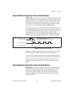
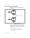
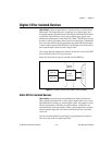
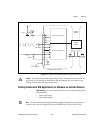
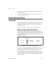
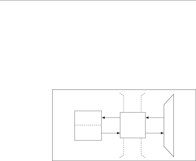
Figure 6-5 shows the circuitry of one bank-isolated DIO line.
Figure 6-5. Isolated S Series Devices Digital I/O Block Diagram
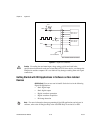
Static DIO for Isolated Devices
(NI 6154 Only) Isolated devices have unidirectional digital lines that are
either static digital inputs (DI) or static digital outputs (DO). You can use
DI and DO lines to monitor or control digital signals. All samples of static
DI lines and updates of DO lines are software-timed. All DO lines are
controlled by the same output enable. When a digital output line is enabled,
all other digital output lines will also be enabled and driven to a default
value of 0.
You can select the up/down control input of general-purpose counters 0
and 1 from any of the six digital input lines.
Isolation
Barrier
Digital
Isolators
PFI/
Static DI
I/O Connector
PFI/
Static DO