


Chapter 5 Analog Output
© National Instruments Corporation 5-5 NI 6124/6154 User Manual
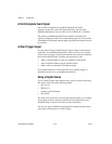
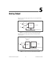
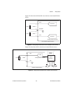
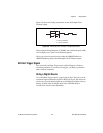
Figure 5-3 shows how AO 0 and AO 1 are wired on a non-isolated S Series
device.
Figure 5-3. Analog Output Connections for Non-Isolated S Series Devices
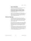
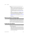
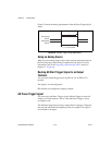
Figure 5-4 shows how AO 0 is wired on an isolated S Series device.
Figure 5-4. Analog Output Connections for Isolated S Series Devices
+
–
+
–
Channel 0
Channel 1
Load
Load
VOUT 0
VOUT 1
AO 1
AO GND
AO 0
Analog Output Channels
Non-Isolated S Series Device
+
–
Lo
ad
VOUT
AO–
AO+
Analog Output Channel
Isolated S Series Device
DAC
Digital
Isolators
Isolation
Barrier