


Chapter 7 Counters
NI 6124/6154 User Manual 7-12 ni.com
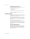
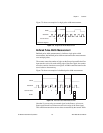
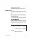
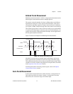
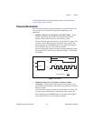
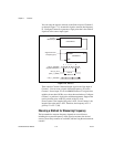
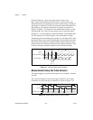
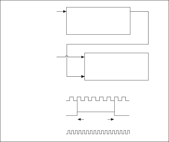
You can route the signal to measure to the Source input of Counter 0,
as shown in Figure 7-13. Assume this signal to measure has frequency
F1. Configure Counter 0 to generate a single pulse that is the width of
N periods of the source input signal.
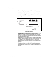
Figure 7-13. Method 3
Then route the Counter 0 Internal Output signal to the Gate input of
Counter 1. You can route a signal of known frequency (F2) to the
Counter 1 Source input. F2 can be 80MHzTimebase. For signals that
might be slower than 0.02 Hz, use a slower known timebase. Configure
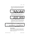
Counter 1 to perform a single pulse-width measurement. Suppose the
result is that the pulse width is J periods of the F2 clock.
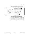
From Counter 0, the length of the pulse is N/F1. From Counter 1, the
length of the same pulse is J/F2. Therefore, the frequency of F1 is
given by F1 = F2 * (N/J).
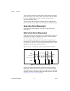
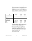
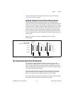
Choosing a Method for Measuring Frequency
The best method to measure frequency depends on several factors
including the expected frequency of the signal to measure, the desired
accuracy, how many counters are available, and how long the measurement
can take.
SOURCE OUT
COUNTER 0
SOURCE
GATE
OUT
COUNTER 1
Signal to
Measure (F1)
Signal of Known
Frequency (F2)
CTR_0_SOURCE
(Signal to Measure)
CTR_0_OUT
(CTR_1_GATE)
CTR
_
1
_
SOURCE
Interval
to Measure
0 1 2 3 … N