


Chapter 7 Counters
NI 6124/6154 User Manual 7-24 ni.com
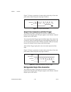
Frequency Output can be routed out to any PFI <0..15> or RTSI <0..7>
terminal. All PFI terminals are set to high-impedance at startup. The FREQ
OUT signal also can be routed to DO Sample Clock and DI Sample Clock.
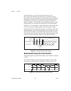
In software, program the frequency generator as you would program one of
the counters for pulse train generation.
For information about connecting counter signals, refer to the Default
Counter/Timer Pinouts section.
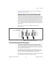
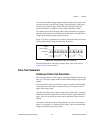
Frequency Division
The counters can generate a signal with a frequency that is a fraction of
an input signal. This function is equivalent to continuous pulse train
generation. Refer to the Continuous Pulse Train Generation section for
detailed information.
For information about connecting counter signals, refer to the Default
Counter/Timer Pinouts section.
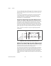
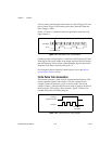
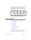
Pulse Generation for ETS
In the equivalent time sampling (ETS) application, the counter produces a
pulse on the output a specified delay after an active edge on Gate. After
each active edge on Gate, the counter cumulatively increments the delay
between the Gate and the pulse on the output by a specified amount. Thus,
the delay between the Gate and the pulse produced successively increases.
The increase in the delay value can be between 0 and 255. For instance, if
you specify the increment to be 10, the delay between the active Gate edge
and the pulse on the output will increase by 10 every time a new pulse is
generated.
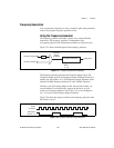
Suppose you program your counter to generate pulses with a delay of 100
and pulse width of 200 each time it receives a trigger. Furthermore, suppose
you specify the delay increment to be 10. On the first trigger, your pulse
delay will be 100, on the second it will be 110, on the third it will be 120;
the process will repeat in this manner until the counter is disarmed. The
counter ignores any Gate edge that is received while the pulse triggered by
the previous Gate edge is in progress.