


Chapter 9 Digital Routing and Clock Generation
NI 6124/6154 User Manual 9-10 ni.com
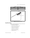
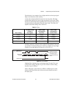
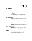
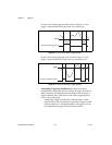
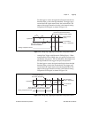
The filter setting for each input can be configured independently. On power
up, the filters are disabled. Figure 9-4 shows an example of a low to high
transition on an input that has its filter set to 125 ns (N = 5).
Figure 9-4. Filter Example
Enabling filters introduces jitter on the input signal. For the 125 ns and
6.425 μs filter settings, the jitter is up to 25 ns. On the 2.56 ms setting,
the jitter is up to 10.025 μs.
When a PFI input is routed directly to RTSI, or a RTSI input is routed
directly to PFI, the S Series device does not use the filtered version of the
input signal.
Refer to the KnowledgeBase document, Digital Filtering with M Series
and CompactDAQ, for more information about digital filters and counters.
To access this KnowledgeBase, go to
ni.com/info and enter the info
code
rddfms.
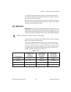
Routing Signals in Software
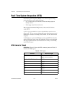
Table 9-4 lists the basic functions you can use to route signals.
Note For more information about routing signals in software, refer to the NI-DAQmx Help
or the LabVIEW Help in version 8.0 or later.
Table 9-4. Signal Routing in Software
Language Function
LabVIEW and NI-DAQmx DAQmx Export Signal.vi and
DAQmx Connect Terminals.vi
C and NI-DAQmx Export_Signal and DAQmx_Connect_Terminals
1 2 3 1 4 1 2 3 4 5
RT
S
I, PFI, or
PXI_STAR Terminal
Filter Clock
(40 MHz)
Filtered Input
Filtered input goes
high when terminal
is sampled high on
five consecutive filter
clocks.