


Chapter 6 Digital I/O
NI 6124/6154 User Manual 6-8 ni.com
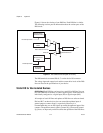
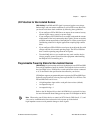
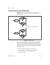
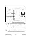
DI Change Detection for Non-Isolated Devices
(NI 6124 Only) You can configure the DAQ device to detect changes in the
DIO signals. Figure 6-3 shows a block diagram of the DIO change
detection circuitry.
Figure 6-3. DI Change Detection
You can enable the DIO change detection circuitry to detect rising edges,
falling edges, or either edge individually on each DIO line. The DAQ
devices synchronize each DI signal to 80MHzTimebase, and then sends the
signal to the change detectors. The circuitry ORs the output of all enabled
change detectors from every DI signal. The result of this OR is the Change
Detection Event signal.
The Change Detection Event signal can do the following:
• Drive any RTSI <0..7>, PFI <0..15>, or PXI_STAR signal
• Drive the DO Sample Clock or DI Sample Clock
• Generate an interrupt
Synch
Synch
P0.0
P0.7
Enable
Enable
Enable
Enable
Change Detection Event