


Chapter 5 Analog Output
© National Instruments Corporation 5-7 NI 6124/6154 User Manual
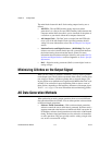
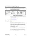
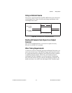
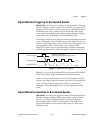
Using an External Source
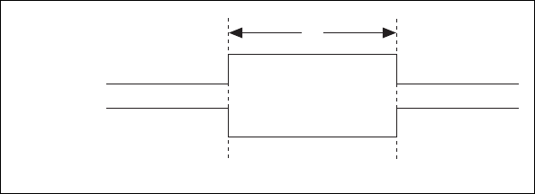
You can use a signal connected to any PFI or RTSI <0..6> pin as the source
of AO Sample Clock. Figure 5-6 shows the timing requirements of the
AO Sample Clock source.
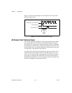
Figure 5-6. AO Sample Clock Timing Requirements
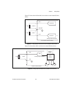
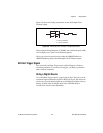
Routing AO Sample Clock Signal to an Output
Terminal
You can route ao/SampleClock (as an active low signal) out to any
PFI <0..15> or RTSI <0..7> terminal.
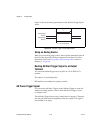
Other Timing Requirements
A counter on your device internally generates AO Sample Clock unless you
select some external source. The AO Start Trigger signal starts this counter.
It is stopped automatically by hardware after a finite acquisition completes
or manually through software. When using an internally generated
AO Sample Clock in NI-DAQmx, you can also specify a configurable
delay from the AO Start Trigger to the first AO Sample Clock pulse. By
default, this delay is two ticks of the AO Sample Clock Timebase signal.
Rising-Edge
Polarity
Falling-Edge
Polarity
t
w
= 10 ns minimum
t
w