Index
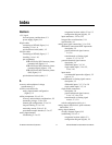
SCB-68 Shielded Connector Block User Manual I-4 ni.com
selecting resistor, 5-17
theory of operation, 5-16 to 5-17
D
DAC0OUT signal
component location in DIFF input mode
(table), 5-3
configuration diagram (figure), 5-4
DAC1OUT signal component location
(table), 5-3
Declaration of Conformity (DoC), F-1
desoldering and soldering, E-1 to E-2
differential connections (DIFF input mode)
component locations for analog input
channels (table), 5-2 to 5-3
DAC0OUT and DAC1OUT signal
component locations (table), 5-3
definition (table), 3-2
description, 3-5
ground-referenced signal sources,
3-4, 3-6
input attenuators, 5-21
lowpass filter, 5-12
measuring 4-20 mA current, 5-18
nonreferenced or floating signal sources,
3-3, 3-7 to 3-8
open thermocouple detection, 5-6
recommended configuration (figure), 3-2
temperature sensor switch configuration
(figure), 4-3
when to use, 3-5
digital input channels
input attenuators, 5-22, 5-24
lowpass filter considerations, 5-12
PFIO/TRIG1 configuration (figure), 5-4
digital I/O (DIO) devices, quick reference
label (table), 1-3
digital signal connections
description, 3-11 to 3-12
switch settings (table), 4-4
digital trigger
circuitry diagram (figure), D-2
input signals, lowpass filtering,
5-15 to 5-16
documentation
conventions used in manual, xi
NI documentation, xii
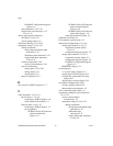
E
E series devices, quick reference label (table),
1-2to1-4, B-2
electromagnetic compatibility
specifications, A-3
environment specifications, A-2
environmental noise. See noise
F
floating signal sources
bias resistors, 3-7
description, 3-3
differential inputs, 3-3, 3-7 to 3-8
recommended configuration (figure), 3-2
single-ended connections (RSE input
mode), 3-3, 3-9
fuse
location (figure), 2-2
specifications, A-1 to A-2
troubleshooting, C-1
G
ground-referenced signal sources
description, 3-4
differential inputs, 3-4, 3-6
recommended configuration (figure), 3-2
single-ended inputs, 3-4 to 3-5,
3-9to3-10


