


Chapter 5 Adding Components for Special Functions
© National Instruments Corporation 5-21 SCB-68 Shielded Connector Block User Manual
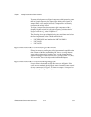
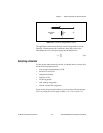
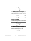
Figure 5-20. SCB-68 Circuit Diagram for SE Input Attenuation
Install resistors in positions B and F, or positions D and G, depending on
the channel you are using on the SCB-68. Use Equations 5-14 or 5-15 to
calculate the gain of the circuit:
(5-14)
(5-15)
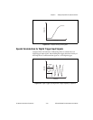
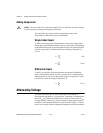
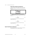
Differential Input Attenuators
To build a three-resistor circuit for attenuating voltages at the differential
inputs of the SCB-68, refer to Figure 5-21.
Figure 5-21. SCB-68 Circuit Diagram for DIFF Input Attenuation
Install resistors in positions E, F, and G of the chosen differential channel
pair. Use Equation 5-16 to determine the gain of the circuit:
(5-16)
R
F,G
R
B,D
V
in
V
m
ACH<
i
>
AIGND
+
–
+
–
G
R
B
R
B
R
F
+()
------------------------=
G
R
D
R
D
R
G
+()
-------------------------=
R
F
R
E
V
in
V
m
ACH<
i
>
ACH<
i
+8>
+
–
+
–
R
G
G
R
E
R
E
R
F
R
G
++()
-------------------------------------=