


Chapter 5 Adding Components for Special Functions
© National Instruments Corporation 5-5 SCB-68 Shielded Connector Block User Manual
Accuracy and Resolution Considerations
When you measure voltage to subsequently measure current, take the
following steps to maximize measurement accuracy:
1. Refer to the accuracy tables in Appendix A, Specifications, of the DAQ
device user manual at
ni.com/manuals.
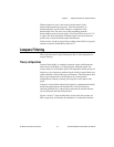
2. Use Equation 5-1 to determine the code width, which is the smallest
signal change that a system can detect.
3. Divide code width by the resistor value to determine the minimum
current value you can measure.
(5-1)
In Equation 5-1, range defines the values between and including the
minimum and maximum voltages that the ADC can digitize. For example,
the range is 20 when you measure a signal between –10 to 10 V. Gain,
which is determined by the input limits of the application, is a value you
apply to amplify or attenuate the signal.
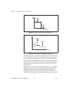
Gain is expressed in decibels and is defined as:
(5-2)
Resolution, or the smallest signal increment that can be detected by a
measurement system, is either 12 or 16 bits, depending on the DAQ device.
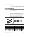
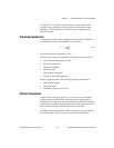
Open Thermocouple Detection
As an option, you can build open thermocouple detection circuitry by
connecting a high-value resistor between the positive input and +5V.
A resistor of a few MΩ or more is sufficient, but a high-value resistor
allows you to detect an open or defective thermocouple. If the
thermocouple opens, the voltage measured across the input terminals rises
to +5 V, a value much larger than any legitimate thermocouple voltage.
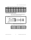
You can create a bias current return path by using a 100 kΩ resistor
between the negative input and AIGND.
Code Width
Range
Gain 2
Resolution
×
-------------------------------------------=
Gain 20 Log f()=