


© National Instruments Corporation 5-1 SCB-68 Shielded Connector Block User Manual
5
Adding Components
for Special Functions
This chapter describes how to condition signals by adding components to
the open component locations of the SCB-68. To add components to these
locations, the DAQ device must support switch configurations 2, 3, or 4 in
Table 2-1, Switch Configurations and Affected Signals.
Caution Add components at your own risk.
The following signal conditioning applications are described in this
chapter:
• Analog input
– Open thermocouple detection
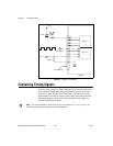
– Lowpass filtering
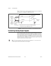
– Measuring 4–20 mA current
– Voltage attenuation
• Analog output
– Lowpass smoothing filter
– Voltage attenuation
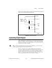
• Digital input
– Lowpass digital filter
– Voltage attenuation
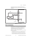
In addition to the applications described in this chapter, many other types
of signal conditioning can be built using the component pads and the
general-purpose breadboard area of the SCB-68. Refer to Appendix E,
Soldering and Desoldering on the SCB-68, for more information about
adding components and for soldering and desoldering instructions.
After building one of the applications described in this chapter or your own
custom circuitry, refer to the Configuring the SCB-68 section of Chapter 1,
Introduction, for instructions about how to configure the SCB-68 in MAX.