


Chapter 5 Adding Components for Special Functions
SCB-68 Shielded Connector Block User Manual 5-12 ni.com
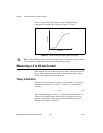
For any type of lowpass filter, use Equation 5-5 to determine the cut-off
frequency (f
c
).
(5-5)
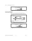
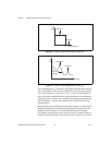
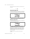
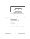
Single-Ended Lowpass Filter
To build a single-ended lowpass filter, refer to Figure 5-12. Add the resistor
to position B or D, depending on the AI channel you are using. Add the
capacitor to position F or G, depending on the AI channel you are using.
Figure 5-12. SCB-68 Circuit Diagram for a Single-Ended Lowpass Filter
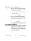
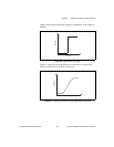
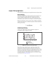
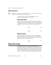
Differential Lowpass Filter
To build a differential lowpass filter, refer to Figure 5-13. Add the resistor
to position E and the capacitor to position F.
Figure 5-13. SCB-68 Circuit Diagram for a Differential Lowpass Filter
Analog Output and Digital Input Lowpass Filtering
For DAC0OUT, add the resistor to position RC3 and the capacitor to
position R3. For DAC1OUT, add the resistor to position RC2 and the
capacitor to position R2.
For TRIG1, add the resistor to position RC1 and the capacitor to
position R1.
f
c
1
2πRC
---------------=
C
F,G
R
B,D
V
in
V
m
ACH<
i
>
AIGND
+
–
+
–
C
F
R
E
V
in
V
m
ACH<
i
>
ACH<
i
+8>
+
–
+
–