


Chapter 5 Adding Components for Special Functions
SCB-68 Shielded Connector Block User Manual 5-18 ni.com
Adding Components
Caution Do not exceed ±10 V at the analog inputs. NI is not liable for any device damage
or personal injury resulting from improper connections.
You can build a one-resistor circuit for measuring current at the
single-ended or differential inputs of the SCB-68.
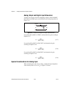
Single-Ended Inputs
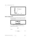
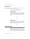
To build a one-resistor circuit that measures current at the single-ended
analog inputs of the SCB-68, add the resistor to position B or D depending
on the channel being used. Leave the jumpers in place for channel positions
F and G, respectively. Calculate the current according to Equation 5-9
or 5-10.
(5-9)
(5-10)
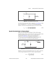
Differential Inputs
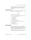
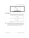
To build a one-resistor circuit that measures current at the differential
inputs of the SCB-68, add the resistor to position E for each differential
channel pair that is used. Leave the jumpers in place for positions F and G.
Calculate the current according to Equation 5-11:
(5-11)
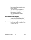
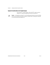
Attenuating Voltage
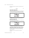
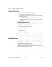
This section describes how to add components for attenuating, or
decreasing the amplitude of, a voltage signal. Transducers can output more
than 10 V
DC
per channel, but DAQ devices cannot read more than 10 V
DC
per input channel. Therefore, you must attenuate output signals from the
transducer to fit within the DAQ device specifications. Figure 5-19 shows
how to use a voltage divider to attenuate the output signal of the transducer.
I
V
m
R
B
------=
I
V
m
R
E
------=
I
V
m
R
E
------=