


© National Instruments Corporation E-1 SCB-68 Shielded Connector Block User Manual
E
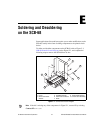
Soldering and Desoldering
on the SCB-68
Some applications discussed here require you to make modifications to the
SCB-68, usually in the form of adding components to the printed circuit
device.
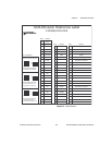
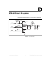
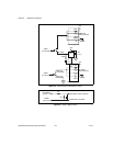
To solder and desolder components on the SCB-68, refer to Figure 2-1,
SCB-68 Printed Circuit Diagram, and to Figure E-1, and complete the
following steps to remove the SCB-68 from its box.
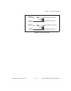
Figure E-1. SCB-68 Parts Locator Diagram
Note
If the kit is missing any of the components in Figure E-1, contact NI by selecting
Contact NI at
ni.com.
1 Quick Reference Label
2Cover
3 68-Pin Connector
Screws
4 Lock Washers
5 Shielding Screws
6 68-Pin I/O Connector
7Base
8 Strain-Relief Bars
9 Strain-Relief Screws
10 Circuit Card Assembly
2
3
4
5
7
9
8
1
10
6