


Chapter 3 Connecting Signals
© National Instruments Corporation 3-11 SCB-68 Shielded Connector Block User Manual
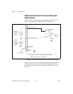
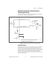
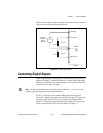
Figure 3-6 shows how to make AO connections and the external reference
connection to the SCB-68 and the DAQ device.
Figure 3-6. Connecting AO Signals
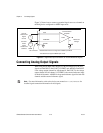
Connecting Digital Signals
When using the SCB-68 with a 68-pin or 100-pin DAQ device, the DIO
signals are DIO<0..7> and DGND. DIO<0..7> are the eight single-ended
DIO lines, and DGND is the ground reference. You can program all lines
individually to be inputs or outputs.
Note For more information, refer to the device user manual at ni.com/manuals for
detailed signal description and connection information.
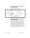
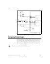
Figure 3-7 illustrates several common DIO applications and signal
connections. Digital input applications include receiving TTL signals and
sensing external device states such as the state of the switch shown in
Figure 3-7. Digital output applications include sending TTL signals and
driving external devices such as the LED shown in Figure 3-7.
External
Reference
Signal
(optional)
V
ref
+
–
Load
Load
VOUT 0
VOUT 1
+
–
+
–
AOGND
DAC1OUT
SCB-68
DAC0OUT
EXTREF