


Chapter 5 Adding Components for Special Functions
SCB-68 Shielded Connector Block User Manual 5-2 ni.com
You can create virtual channels in MAX to map your voltage ranges to the
type of transducer that you are using or to create a custom scale.
Channel Pad Configurations
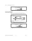
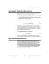
When you use the SCB-68 with a 68-pin or 100-pin DAQ device, you can
use the component pads on the SCB-68 to condition 16 AI channels, two
AO channels, and PFI0/TRIG1.
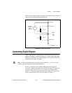
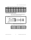
Conditioning Analog Input Channels
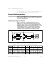
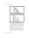
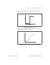
Figure 5-1 illustrates the AI channel configuration. ACH<i> and
ACH<i+8> can be used as either a differential channel pair or as two
single-ended channels. Table 5-1 correlates the component labels of the
SCB-68 to component locations A–G for differential channels 0–7. In the
component names in Table 5-1, R denotes a resistor, and C denotes a
capacitor. Component locations labeled RCX provide sockets for two
components, a resistor and a capacitor, to be connected in parallel.
Figure 5-1. Analog Input Channel Configuration Diagram for ACH<i> and ACH<i+8>
Table 5-1. Component Location for Analog Input Channels in DIFF Input Mode
Channel A B C D E F G
ACH0 R22 RC12 RC13 R23 RC4 R4 R5
ACH1 R24 RC14 RC15 R25 RC5 R6 R7
ACH2 R26 RC14 RC17 R27 RC6 R8 R9
ACH3 R28 RC18 RC19 R29 RC7 R10 R11
+5V ACH<
i
>
AIGND ACH<
i
+8>
(C)
(B)
(D)
(E)
(G)
(F)
(A)