


© National Instruments Corporation 5-1 7344/7334 Hardware User Manual
5
Signal Connections
This chapter describes how to make input and output signal connections
directly to the 7344/7334 and briefly describes the associated 7344/7334
I/O circuitry.
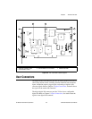
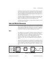
The 7344/7334 has three connectors that handle all signals to and from the
external motion system:
• 68-pin motion I/O connector
• 68-pin digital I/O connector
• RTSI connector
You can connect to your motion system with cables and accessories,
varying from simple screw terminal blocks to enhanced UMI units and
drives.
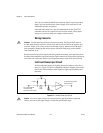
Caution
Turn off power to all devices when connecting or disconnecting the
7344/7334 controller motion I/O and auxiliary digital I/O cables. Failure to do so may
damage the 7344/7334 controller.
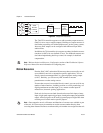
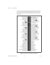
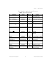
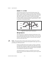
Motion I/O Connector
The motion I/O connector contains all of the signals required to control up
to four axes of servo (7344 only) and stepper motion including the
following features:
• Motor command analog and stepper outputs
• Encoder feedback inputs
• Forward, home, and reverse limit inputs
• Breakpoint outputs
• Trigger inputs
• Inhibit outputs
This connector also contains four channels of 12-bit A/D inputs for analog
feedback or general-purpose analog input.