


Chapter 5 Signal Connections
© National Instruments Corporation 5-5 7344/7334 Hardware User Manual
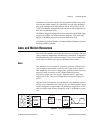
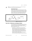
• Axis <1..4> Inhibit—Use the inhibit output signals to control the
enable/inhibit function of a servo amplifier or stepper driver. When
properly connected and configured, the inhibit function causes the
connected motor to be de-energized and its shaft turns freely. These
open-collector inhibit signals feature 64 mA current sink capability
with built-in 3.3 kΩ pull-up resistors to +5 V, and can directly drive
most driver/amplifier inhibit input circuits.
While the industry standard for inhibits is active-low (inverting), these
outputs have programmable polarity and can be set to active-high
(non-inverting) for increased flexibility and unique drive
compatibility.
Inhibit output signals can be activated automatically upon a Kill
Motion command or any motion error that causes a kill motion
condition (for example, following error trip). You can also directly
control the inhibit output signals to enable or disable a driver or
amplifier.
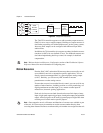
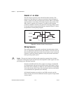
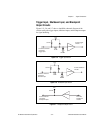
Limit and Home Inputs
The following signals control limit and home inputs:
• Axis <1..4> Forward Limit Input
• Axis <1..4> Home Input
• Axis <1..4> Reverse Limit Input
These inputs are typically connected to limit switches located at physical
ends of traveland/or at aspecific home position. Limit and home inputs can
be software enabled and disabled at any time. When enabled, an active
transition on a limit or home input causes a full torque halt stop of the
associated motor axis. In addition, an active forward or reverse limit input
impedes future commanded motion in that direction for as long as the
signal is active.
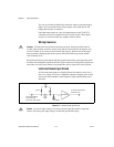
Note
Limit and home inputs are digitally filtered and must remain active for at least 1 ms
to be recognized. Active signals should remain active to prevent motion from proceeding
further into the limit. Pulsed limit signals stop motion, but they do not prevent further
motion in that direction if another move is started.
The input polarity of these signals is software programmable for active-low
(inverting) or active-high (non-inverting).