


Chapter 5 Signal Connections
© National Instruments Corporation 5-11 7344/7334 Hardware User Manual
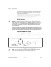
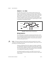
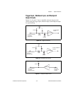
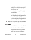
Trigger Input, Shutdown Input, and Breakpoint
Output Circuits
Figures 5-5, 5-6, and 5-7 show a simplified schematic diagram of the
circuits used by the trigger inputs, shutdown inputs, and breakpoint outputs
for signal buffering.
Figure 5-5. Trigger Input Circuit
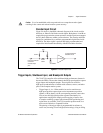
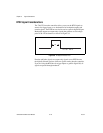
Figure 5-6. Shutdown Input Circuit
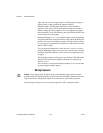
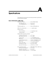
Figure 5-7.
Breakpoint Output Circuit
74HC244
1k
Ω
1/8 W
From the external
connector
trigger pins
To the trigger
circuits
DGND
Vcc
3.3 k
Ω
74HC244
1kΩ
1/8 W
From the external
connector
shutdown pin
To the shutdown
circuits
DGND
Vcc
3.3 kΩ
74AS760
To the external
connector
breakpoint pins
From the
breakpoint
circuits
Vcc
3.3 kΩ