


Chapter 5 Signal Connections
© National Instruments Corporation 5-3 7344/7334 Hardware User Manual
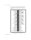
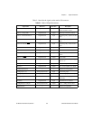
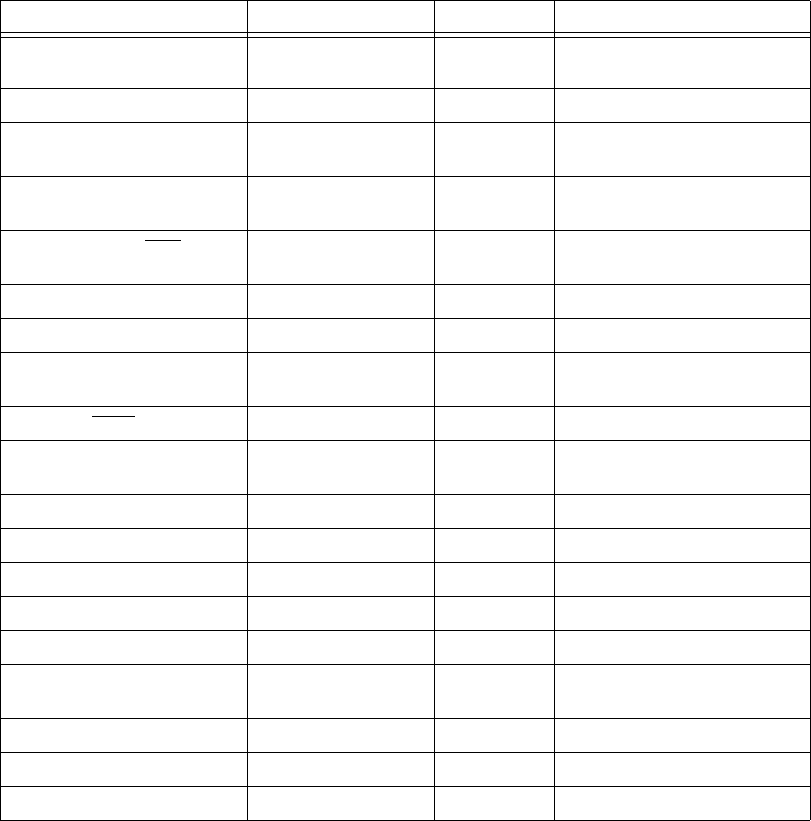
Table 5-1 describes the signals on the motion I/O connector.
Table 5-1. Motion I/O Signal Connections
Signal Name Reference Direction Description
Axis <1..4> Dir (CCW) Digital Ground Output Motor direction or
counter-clockwise control
Axis <1..4> Step (CW) Digital Ground Output Motor step or clockwise control
Axis <1..4> Encoder Phase A Digital Ground Input Closed-looponly—phaseAencoder
input
Axis <1..4> Encoder Phase B Digital Ground Input Closed-looponly—phaseB encoder
input
Axis<1..4> Encoder Index Digital Ground Input Closed-loop only—index encoder
input
Axis <1..4> Home Switch Digital Ground Input Home switch
Axis <1..4> Forward Limit Switch Digital Ground Input Forward/clockwise limit switch
Axis <1..4> Reverse Limit Switch Digital Ground Input Reverse/counter-clockwise limit
switch
Axis <1..4> Inhibit Digital Ground Output Drive inhibit
Trigger <1..4> Digital Ground Input High-speed position capture trigger
input <1..4>
Breakpoint <1..4> Digital Ground Output Breakpoint output <1..4>
Host +5 V Digital Ground Output +5 V—host computer +5 V supply
Analog Input Ground — — Reference for analog inputs
Analog Input <1..4> Analog Input Ground Input 12-bit analog input
Analog Output <1..4> Analog Output Ground Output 16-bit analog output (7344 only)
Analog Output Ground — — Reference for analog outputs
(7344 only)
Shutdown Digital Ground Input Controlled device shutdown
Analog Reference (output) Analog Input Ground Output +7.5 V—analog reference level
Digital Ground — — Reference for digital I/O