


Chapter 5 Signal Connections
7344/7334 Hardware User Manual 5-8 ni.com
Encoder <1..4> Index
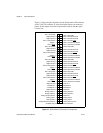
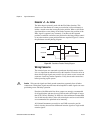
The Index input is primarily used with the Find Index function. This
function uses the number of counts per revolution (or linear distance) to
initiate a search move that locates the index position. When a valid Index
signal transition occurs during a Find Index sequence, the position of the
Index signal is captured very accurately. You then use this captured
position to establish a reference zero position for absolute position control
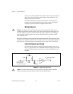
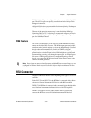
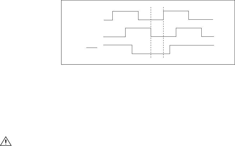
or any other motion system position reference required. Figure 5-3 shows
the quadrature encoder phasing diagram.
Figure 5-3. Quadrature Encoder Phasing Diagram
Wiring Concerns
The encoder inputs are connected to quadrature decoder/counter circuits.
It is very important to minimize noise at this interface. Excessive noise on
these encoder input signals may result in loss of counts or extra counts and
erroneous closed-loop motion operation. Verify the encoder connections
before powering up the system.
Caution
Wire encoder signals and their ground connections separately from all other
connections. Wiring these signals near the motor drive/amplifier or other signals can cause
positioning errors and faulty operation.
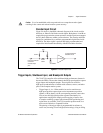
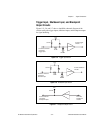
Encoders with differential line driver outputs are strongly recommended
for all applications and must be used if the encoder cable length is longer
than 10 ft (3.05 m). Shielded, 24 AWG wire is the minimum recommended
size for the encoder cable. Cables with twisted pairs and an overall shield
are recommended for optimized noise immunity.
All National Instruments power drives and UMI accessories provide
built-in circuitry that converts differential encoder signals to single-ended
encoder signals.
Phase A
Phase B
Index