


Chapter 5 Signal Connections
© National Instruments Corporation 5-9 7344/7334 Hardware User Manual
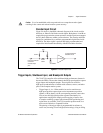
Caution
Use of an unshielded cable can permit noise to corrupt the encoder signals
resulting in lost counts and reduced motion system accuracy.
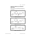
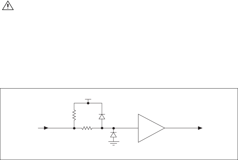
Encoder Input Circuit
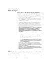
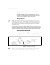
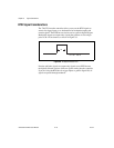
Figure 5-4 shows a simplified schematic diagram of the circuit used for
the Phase A, Phase B, and Index encoder inputs. Both phases A and B are
required for proper encoder counter operation, and the signals must support
the 90° phase difference within system tolerance. The encoder and Index
signals are conditioned by a software-programmable digital filter inside
the FPGA. The Index signal is optional but highly recommended and
required for initialization functionality with the Find Index function.
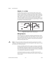
Figure 5-4. Encoder Input Circuit
Trigger Inputs, Shutdown Input, and Breakpoint Outputs
The 7344/7334 controller offers additional high-performance features in
the encoder FPGA. Theencoder channels have high-speed position capture
trigger inputs and breakpoint outputs. These signals are useful for
high-speed synchronization of motion with actuators, sensors, and other
parts of the complete motion system:
• Trigger Input <1..4>—When enabled, an active transition on a
high-speed position capture input causes instantaneous position
capture (<100 ns latency) of the corresponding encoder count value.
You can use this high-speed position capture functionality for
applications ranging from simple position tagging of sensor data
to complex camming systems with advance/retard positioning and
registration. An available 7344/7334 controller position mode is to
move an axis Relative to Captured Position.
The polarity of the trigger input is programmable in software as
active-low (inverting) or active-high (non-inverting), rising or falling
74HC244
1k
Ω
1/8 W
From the external
connector
encoder input
pins
To the quadrature
decoder circuit
DGND
Vcc
3.3 k
Ω