


Chapter 5 Signal Connections
7344/7334 Hardware User Manual 5-6 ni.com
You can use software disabled limit and home inputs as general-purpose
inputs. You can read the status of these inputs at any time and set and
change their polarity as required.
Limit and home inputs are a per axis enhancement on the 7344/7334
controllers and are not required for basic motion control. These inputs
are part of a system solution for complete motion control.
Wiring Concerns
Cautions
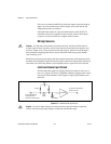
For the end of travel limits to function correctly, the forward limit must be
located at the forward or positive end of travel and the reverse limit at the negative end
of travel. Failure to do so may result in motion that stops at, but then travels through, a
limit, potentially damaging the motion system. Miswired limits may prevent motion
from occurring at all.
Keep limit and home switch signals and their ground connections wired separately from
the motor driver/amplifier signal and encoder signal connections. Wiringthese signals near
each other can cause faulty motion system operation due to signal noise and crosstalk.
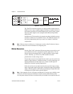
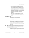
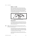
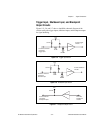
Limit and Home Input Circuit
All limit and home inputs are digitally filtered and must be active for at
least 1 ms. Figure 5-2 shows a simplified schematic diagram of the circuit
used by the limit and home switch inputs for input signal buffering and
detection.
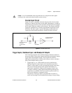
Figure 5-2. Limit and Home Input Circuit
Caution
Excessive input voltages can cause erroneous operation and/or component
failure. Verify that your input voltage is within the specification range.
74HC244
1kΩ
1/8 W
From the external
connector limit
and home switch pins
To the limit and home
switch circuits
DGND
Vcc
3.3 kΩ