Chapter 10 Digital Routing and Clock Generation
© National Instruments Corporation 10-3 NI 6238/6239 User Manual
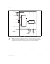
10 MHz Reference Clock
The 10 MHz reference clock can be used to synchronize other devices to
your M Series device. The 10 MHz reference clock can be routed to the
RTSI <0..7> terminals. Other devices connected to the RTSI bus can use
this signal as a clock input.
The 10 MHz reference clock is generated by dividing down the onboard
oscillator.
Synchronizing Multiple Devices
With the RTSI bus and the routing capabilities of M Series devices, there
are several ways to synchronize multiple devices depending on your
application.
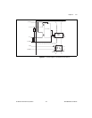
To synchronize multiple devices to a common timebase, choose one
device—the initiator—to generate the timebase. The initiator device routes
its 10 MHz reference clock to one of the RTSI <0..7> signals.
All devices (including the initiator device) receive the 10 MHz Reference
Clock from RTSI. This signal becomes the external reference clock. A PLL
on each device generates the internal timebases synchronous to the external
reference clock.
On PXI systems, you also can synchronize devices to PXI_CLK10. In this
application the PXI chassis acts as the initiator. Each PXI module routes
PXI_CLK10 to its external reference clock.
Another option in PXI systems is to use PXI_STAR. The Star Trigger
controller device acts as the initiator and drives PXI_STAR with a clock
signal. Each target device routes PXI_STAR to its external reference clock.
When all of the devices are using or referencing a common timebase, you
can synchronize operations across them by sending a common start trigger
out across the RTSI bus and setting their sample clock rates to the same
value.
Real-Time System Integration Bus (RTSI)
Real-Time System Integration (RTSI) is set of bused signals among devices
that allow you to do the following.
• Use a common clock (or timebase) to drive the timing engine on
multiple devices


