Chapter 7 Counters
NI 6238/6239 User Manual 7-6 ni.com
Pulse-Width Measurement
In pulse-width measurements, the counter measures the width of a pulse on
its Gate input signal. You can configure the counter to measure the width of
high pulses or low pulses on the Gate signal.
You can route an internal or external periodic clock signal (with a known
period) to the Source input of the counter. The counter counts the number
of rising (or falling) edges on the Source signal while the pulse on the Gate
signal is active.
You can calculate the pulse width by multiplying the period of the Source
signal by the number of edges returned by the counter.
A pulse-width measurement will be accurate even if the counter is armed
while a pulse train is in progress. If a counter is armed while the pulse is in
the active state, it will wait for the next transition to the active state to begin
the measurement.
Single Pulse-Width Measurement
With single pulse-width measurement, the counter counts the number of
edges on the Source input while the Gate input remains active. When the
Gate input goes inactive, the counter stores the count in a hardware save
register and ignores other edges on the Gate and Source inputs. Software
then can read the stored count.
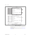
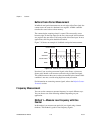
Figure 7-6 shows an example of a single pulse-width measurement.
Figure 7-6. Single Pulse-Width Measurement
Buffered Pulse-Width Measurement
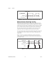
Buffered pulse-width measurement is similar to single pulse-width
measurement, but buffered pulse-width measurement takes measurements
over multiple pulses.
SOURCE
GATE
Counter Value
HW Save Register
10
2
2


