Chapter 5 Analog Output
© National Instruments Corporation 5-5 NI 6238/6239 User Manual
Maximum Working Voltage section of the NI 6238/6239 Specifications. Exceeding the
maximum input supply voltage or maximum working voltage of AO signals distorts the
measurement results. Exceeding the maximum input supply voltage or maximum working
voltage rating also can damage the device and the computer. Exceeding the maximum
output voltage can cause injury and harm the user. NI is not liable for any damage or
injuries resulting from such signal connections.
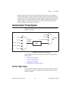
Analog Output Timing Signals
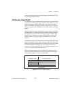
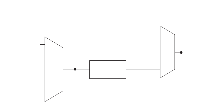
Figure 5-3 summarizes all of the timing options provided by the analog
output timing engine.
Figure 5-3. Analog Output Timing Options
NI 6238/6239 devices feature the following AO (waveform generation)
timing signals.
• AO Start Trigger Signal
• AO Pause Trigger Signal
• AO Sample Clock Signal
• AO Sample Clock Timebase Signal
AO Start Trigger Signal
Use the AO Start Trigger (ao/StartTrigger) signal to initiate a waveform
generation. If you do not use triggers, you can begin a generation with a
software command.
PFI, RTSI
PXI_STAR
20 MHz Timebase
100 kHz Timebase
PXI_CLK10
Programmable
Clock
Divider
ao/Sample
Clock
Timebase
PFI, RTSI
PXI_STAR
Ctr
n
Internal Output
ao/Sample
Clock


