


Chapter 10 Digital Routing and Clock Generation
© National Instruments Corporation 10-5 NI 6238/6239 User Manual
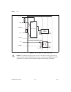
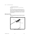
Using RTSI as Outputs
RTSI <0..7> are bidirectional terminals. As an output, you can drive any of
the following signals to any RTSI terminal.
• ai/StartTrigger
• ai/ReferenceTrigger
• ai/ConvertClock*
• ai/SampleClock
• ai/PauseTrigger
• ao/SampleClock*
• ao/StartTrigger
• ao/PauseTrigger
• 10 MHz Reference Clock
• Counter n Source, Gate, Z, Internal Output
• FREQ OUT
• Input PFI <0..5>
Note Signals with a * are inverted before being driven on the RTSI terminals.
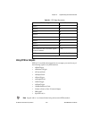
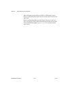
Table 10-1. RTSI Signal Descriptions
RTSI Bus Signal Terminal
RTSI 7 34
RTSI 6 32
RTSI 5 30
RTSI 4 28
RTSI 3 26
RTSI 2 24
RTSI 1 22
RTSI 0 20
Not Connected. Do not connect signals
to these terminals.
1–18
GND 19, 21, 23, 25, 27, 29, 31, 33
Note: RTSI <0..7> and GND are earth/chassis ground-referenced. They are not isolated.