


Chapter 7 Counters
© National Instruments Corporation 7-29 NI 6238/6239 User Manual
• ai/StartTrigger
•PXI_STAR
In addition, Counter 1 Internal Output, Counter 1 Gate, Counter 1 Source,
or Counter 0 Gate can be routed to Counter 0 Aux. Counter 0 Internal
Output, Counter 0 Gate, Counter 0 Source, or Counter 1 Gate can be routed
to Counter 1 Aux.
Some of these options may not be available in some driver software.
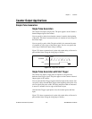
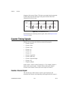
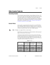
Counter n A, Counter n B, and Counter n Z Signals
Counter n B can control the direction of counting in edge counting
applications.
Use the A, B, and Z inputs to each counter when measuring quadrature
encoders or measuring two pulse encoders.
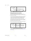
Routing Signals to A, B, and Z Counter Inputs
Each counter has independent input selectors for each of the A, B, and Z
inputs. Any of the following signals can be routed to each input.
•RTSI<0..7>
• Input PFI <0..5>
•PXI_STAR
Routing Counter n Z Signal to an Output Terminal
You can route Counter n Z out to RTSI <0..7>.
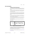
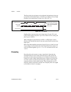
Counter n Up_Down Signal
Counter n Up_Down is another name for the Counter n B signal.
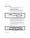
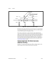
Counter n HW Arm Signal
The Counter n HW Arm signal enables a counter to begin an input or output
function.
To begin any counter input or output function, you must first enable, or arm,
the counter. In some applications, such as buffered semi-period
measurement, the counter begins counting when it is armed. In other
applications, such as single pulse-width measurement, the counter begins