


Configuration and Installation Chapter 2
SCXI-1122 User Manual 2-4 © National Instruments Corporation
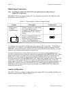
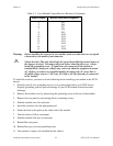
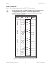
Table 2-2. Jumper W1 Settings
Jumper Description Configuration
Grounding,
shielding, and
reference mode
selection
Unconnected position (factory setting)
W1
B
A
R0
R1 R2
Connects the analog reference to the
analog output ground AOGND (pins 1
and 2 on the rear signal connector).
Select this configuration if you are
using an RSE DAQ board. Do not use
a differential input DAQ board when
jumper W1 is in this position.
B
A
R0
R1 R2
W1
Connects SCXIbus guard to the analog
reference
B
A
R0
R1 R2
W1
W1
Enables the pseudodifferential
reference mode and connects the
analog reference to the OUTREF pin
on the rear signal connector. Select
this mode when the SCXI-1122 has to
operate with DAQ boards that have a
nonreferenced single-ended (NRSE)
input. Do not use differential input
DAQ boards when jumper W1 is in
this position.
B
A
R0
R1 R2
W1
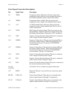
Current-Loop Receivers
The SCXI-1122 has pads for transforming individual channels to current-to-voltage converters.
National Instruments offers an SCXI process current pack, which consists of a package of four
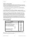
249 Ω, 0.1%, 5 ppm, 1/4 W resistors. You can find the part number for this kit in the Optional
Equipment section of Chapter 1, Introduction. Table 2-3 shows the input channel and its
corresponding resistor reference designator.
Table 2-3. User-Defined Current Receiver Resistors
Input Channel Resistor Reference Designator
0R1
1R2
2R3
3R4
(continues)