


Chapter 4 Theory of Operation
© National Instruments Corporation 4-3 SCXI-1122 User Manual
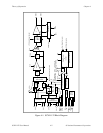
The major components of the SCXI-1122 are as follows:
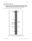
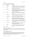
• The rear signal connector
• The SCXIbus connector
• The SCXIbus interface
• The digital control circuitry
• The analog circuitry
The SCXI-1122 consists of 16 isolated multiplexed channels with gains of 0.01, 0.02, 0.05, 0.1,
0.2, 0.5, 1, 2, 5, 10, 20, 50, 100, 200, 500, 1,000, and 2,000, and two isolated excitation channels
with voltage and current excitation. The SCXI-1122 also has a digital section for automatic
control of channel scanning, temperature selection, gain selection, and filter selection.
The remainder of this chapter describes the theory of operation for each of these components.
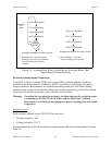
Rear Signal Connector, SCXIbus Connector, and SCXIbus Interface
The SCXIbus controls the SCXI-1122. The SCXIbus interface interfaces the signals of the rear
signal connector to the SCXIbus, allowing a DAQ board to control the SCXI-1122 and the rest of
the chassis.
Digital Control Circuitry
The digital control section consists of the Address Handler Register, the Configuration Register,
the Status Register, and the Module ID Register. The Address Handler Register controls which
register is being addressed. The Configuration Register configures the SCXI-1122 such as gain
selection, shunt calibration, filter bandwidth, two-wire or four-wire scanning, CJS selection, and
auto-zeroing. The Status Register indicates if the SCXI-1122 is done configuring its internal
circuitry or is still in progress of doing so. The Module ID Register contains the module ID A
hex, a code unique to the SCXI-1122. You can read this module ID over the SCXIbus to
determine the type of module in a particular slot.
Analog Circuitry
The analog circuitry consists of a relay multiplexer, a software-programmable gain isolation
amplifier, software-programmable filtering, a temperature sensor channel for cold-junction
compensation, calibration hardware, and voltage and current excitation channel outputs.
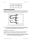
Analog Input Channels
The relay multiplexer feeds into the isolation amplifier. This relay multiplexer can be configured
in two-wire or four-wire mode scanning. In two-wire scan mode all sixteen channels operate as
voltage sense channels. At any point in time one and only one of sixteen channels is connected
to the isolation amplifier. In the four-wire scan mode the sixteen channels are divided into two