


© National Instruments Corporation v SCXI-1122 User Manual
Contents
About This Manual............................................................................................................. ix
Organization of This Manual ......................................................................................... ix
Conventions Used in This Manual................................................................................. x
The National Instruments Documentation Set ............................................................... xi
Related Documentation.................................................................................................. xi
Customer Communication ............................................................................................. xii
Chapter 1
Introduction
.......................................................................................................................... 1-1
What Your Kit Should Contain...................................................................................... 1-1
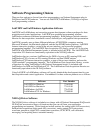
Software Programming Choices .................................................................................... 1-2
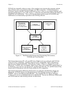
LabVIEW and LabWindows Application Software .......................................... 1-2
NI-DAQ Driver Software................................................................................... 1-2
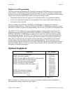
Register-Level Programming ............................................................................. 1-4
Optional Equipment ....................................................................................................... 1-4
Custom Cables ................................................................................................... 1-5
Unpacking ...................................................................................................................... 1-5
Chapter 2
Configuration and Installation
....................................................................................... 2-1
Module Configuration.................................................................................................... 2-1
Digital Signal Connections ................................................................................ 2-3
Analog Configuration ........................................................................................ 2-3
Current-Loop Receivers ......................................................................... 2-4
Hardware Installation ..................................................................................................... 2-6
Chapter 3
Signal Connections
............................................................................................................. 3-1
Front Connector ............................................................................................................. 3-3
Front Signal Connection Descriptions ............................................................... 3-4
Analog Input Channel Signal Connections ............................................ 3-5
Excitation Channel Signal Connections................................................. 3-8
Excitation Level ......................................................................... 3-8
Using the Internal Half-Bridge Completion............................... 3-9
Temperature Sensor Connection ........................................................................ 3-9
Rear Signal Connector ................................................................................................... 3-10
Rear Signal Connection Descriptions ................................................................ 3-11
Analog Output Signal Connections........................................................ 3-11
Digital I/O Signal Connections .............................................................. 3-12
Chapter 4
Theory of Operation
.......................................................................................................... 4-1
Functional Overview...................................................................................................... 4-1
Rear Signal Connector, SCXIbus Connector, and SCXIbus Interface .............. 4-3
Digital Control Circuitry .................................................................................... 4-3
Analog Circuitry ................................................................................................ 4-3
Analog Input Channels........................................................................... 4-3
Excitation Output Channels ................................................................... 4-5