


Calibration Chapter 5
SCXI-1122 User Manual 5-4 © National Instruments Corporation
Excitation Calibration
When using the excitation channels, you must retrieve the correction factors for the current and
voltage from the EEPROM before using them in your transducer conversion formulas. Refer to
your software user manual for how to use the SCXI_Cal_Constants function or VI to
perform this task.
You do not need to read the following section if you are going to use the factory-determined
correction factors and you are using National Instruments software.
If you want to determine a new set of voltage excitation calibration constants and you are using
National Instruments software, use the following procedure:
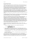
1. Connect a 15 Ω resistor to the excitation channel.
2. Connect the DMM across the 15 Ω load and measure the voltage.
3. Pass this voltage to the SCXI_Cal_Constants function or VI.
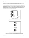
To determine the current excitation calibration constants, follow this procedure:
1. Set your DMM to DC current measurements.
2. Connect the DMM across the IEX+ and IEX- terminals and measure the current.
3. Pass this current to the SCXI_Cal_Constants function or VI.
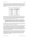
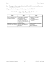
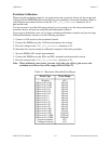
Note: When calibrating your system, you must verify that your offsets, gain errors, and
excitation errors do not exceed the ranges listed in Table 5-1.
Table 5-1. Maximum Allowable Error Ranges
Error Type Error Range
All gains ±2%
Offset at G = 0.01 ±40 mV
Offset at G = 0.02 ±40 mV
Offset at G = 0.05 ±50 mV
Offset at G = 0.1 ±50 mV
Offset at G = 0.2 ±50 mV
Offset at G = 0.5 ±50 mV
Offset at G = 1 ±40 mV
Offset at G = 2 ±40 mV
Offset at G = 5 ±50 mV
Offset at G = 10 ±50 mV
Offset at G = 20 ±50 mV
Offset at G = 50 ±50 mV
Offset at G = 100 ±60 mV
Offset at G = 200 ±70 mV
Offset at G = 500 ±100 mV
Offset at G = 1,000 ±200 mV
Offset at G = 2,000 ±400 mV
Current excitation ±3%
Voltage excitation ±1%