


Index
SCXI-1122 User Manual Index-4 © National Instruments Corporation
ground for better SNR
(illustration), 3-6
floating signal connection referenced
to chassis ground for better SNR
(illustration), 3-6
ground-referenced signal connection
with high common-mode voltage
(illustration), 3-6
pin assignments (illustration), 3-3
signal connection descriptions, 3-4
to 3-5
temperature sensor connection, 3-9
rear signal connector
analog output signal connections,
3-11 to 3-12
digital I/O signal connections, 3-12
to 3-13
pin assignments (illustration), 3-10
SCXIbus to SCXI-1122 rear signal
connector to DAQ board pin
equivalences (table), 3-13
signal descriptions, 3-11
safety warnings, 3-1 to 3-2
SLOT0SEL* signal, 3-11, 3-12
software programming choices
LabVIEW applications software, 1-2
LabWindows applications software, 1-2
NI-DAQ driver software, 1-2 to 1-3
register-level programming, 1-4
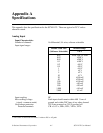
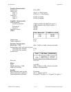
specifications
analog input, A-1 to A-3
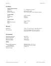
environment, A-3
excitation, A-3
physical, A-3
Status Register, 2-3, 4-3
T
TEMP- signal, 3-4, 3-5
TEMP+ signal, 3-4, 3-5
temperature sensor connection, 3-9, 4-4
theory of operation
analog circuitry, 4-3 to 4-7
analog input channels, 4-3
excitation output channels, 4-3 to 4-7
digital control circuitry, 4-3
functional overview, 4-1 to 4-2
major components of SCXI-1122, 4-3
rear signal connector, 4-3
SCXI-1122 block diagram, 4-2
SCXIbus connector, 4-3
SCXIbus interface, 4-3
U
unpacking the SCXI-1122, 1-5
user-defined current receiver resistors. See
current-loop receivers.
V
VEX- signal, 3-4, 4-5
VEX/2 signal, 3-4
VEX+ signal, 3-4, 4-5
voltage (VEX) excitation channel, 3-8
W
Wheatstone bridge, 4-5