


Chapter 2 Configuration and Installation
© National Instruments Corporation 2-5 SCXI-1122 User Manual
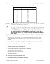
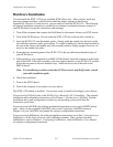
Table 2-3. User-Defined Current Receiver Resistors (Continued)
Input Channel Resistor Reference Designator
4R5
5R6
6R7
7R8
8R9
9 R10
10 R11
11 R12
12 R13
13 R14
14 R17
15 R18
Warning: Before installing the resistors in your module, make sure that there are no signals
connected to your module front connector.
!
SHOCK HAZARD–This unit should only be opened by qualified personnel aware of
the dangers involved. Disconnect all power before removing the cover. Always
install the grounding screw. If signal wires are connected to the module or
terminal block, dangerous voltages may exist even when the equipment is turned
off. Before you remove any installed module, disconnect the AC power line or
any high-voltage sources (
≥
30 Vrms, 42.4 Vpk or 60 Vdc) that may be connected
to the module.
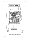
To install the resistors, you need to do the following before installing your module in the SCXI
chassis:
1. Ground yourself via a grounding strap or via a ground connected to your SCXI chassis.
Properly grounding yourself prevents damage to your SCXI module from electrostatic
discharge.
2. Remove the module cover by unscrewing the grounding screw at the rear of the module.
3. Remove the rear panel by unscrewing the two remaining screws.
4. Slide the module out of its enclosure.
5. Insert the resistor(s) into the appropriate pad.
6. Solder the leads to the pads on the solder side of the module.
7. Trim the leads to 0.06 in. maximum.
8. Slide the module back into its enclosure.
9. Reinstall the rear panel.
10. Reinstall the top cover and grounding screw.
11. Your module is ready to be installed into the chassis.