


Chapter 3 Signal Connections
© National Instruments Corporation 3-3 SCXI-1122 User Manual
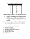
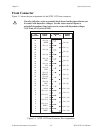
Front Connector
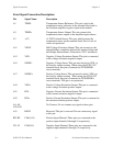
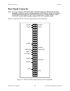
Figure 3-1 shows the pin assignments for the SCXI-1122 front connector.
!
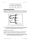
If a relay fails there exists a potential shock hazard on the inputs that are not
in contact with hazardous voltages. For this reason treat all inputs as
potentially hazardous if any inputs are in contact with hazardous voltages
(
≥
30 Vrms, 42.4 Vpk or 60 Vdc).
Pin
Number
Signal
Name
Column
A B C
Signal
Name
32
31
30
29
28
27
26
25
24
23
22
21
20
19
18
17
16
15
14
13
12
11
10
9
8
7
6
5
4
3
2
1
CH+ (0)
RSVD
CH+ (1)
CH+ (2)
CH+ (3)
CH+ (4)
IEX+
CH+ (5)
IEX-
CH+ (6)
VEX+
CH+ (7)
SENSE+
CH+ (8)
SENSE -
CH+ (9)
VEX -
CH+ (10)
CH - (0)
CH - (1)
CH - (2)
CH - (3)
CH - (4)
CH - (5)
CH - (6)
CH - (7)
CH - (8)
CH - (9)
CH - (10)
CH - (11)
CH - (12)
CH - (13)
CH - (14)
CH - (15)
VEX/2
CH+ (11)
CH+ (12)
+5 V
CH+ (13)
CH+ (14)
TEMP+
TEMP-
CH+ (15)
Figure 3-1. SCXI-1122 Front Connector Pin Assignments