


Chapter 4 Theory of Operation
© National Instruments Corporation 4-5 SCXI-1122 User Manual
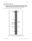
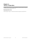
Excitation Output Channels
In addition to the isolated input channels, the SCXI-1122 has isolated excitation channels, one
3.333 V voltage output source and one 1 mA current output source. Both–like the relay input
channel–have a 480 Vrms common-mode voltage with respect to earth ground and
250 Vrms common-mode voltage between each other and any other channel. Both channels are
overvoltage protected to 250 Vrms and are current limited. The voltage excitation channel is
provided for transducers, such as strain gauges, which need voltage excitation to operate
properly. The maximum current sourcing that this channel can provide is 225 mA. Exceeding
this limit will cause the channel to lose regulation. This channel has four terminals, two sense
terminals (SENSE+ and SENSE-) and two excitation terminals (VEX+ and VEX-). This is done
to provide remote load regulation. For proper operation, the SENSE+ terminal must always be
connected to the VEX+, and the SENSE- terminal to the VEX-. Refer to the SCXI-1322
Terminal Block Installation Guide for further details on using the sense terminals for remote load
sensing.
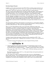
One of the primary applications of this channel is to provide power to a strain gauge configured
in a Wheatstone bridge. To permit verification of proper bridge operation, we have provided you
with shunt calibration means. This can be done programmatically.
When you select shunt calibration while you are performing a Wheatstone bridge strain
measurement , a 301 kΩ 1% resistor internally shunts across the strain gauge between the VEX+
and the CH+; this resistor is socketed to permit you to change its value to meet your
requirements. If you are performing several strain measurements, you can enable the shunt
calibration then proceed with scanning all of the channels of interest. When you have completed
your check, you can disable the shunt calibration and proceed with your measurement. Notice
that when you are either enabling or disabling the shunt calibration resistor, you must wait 1 s if
you have selected 4 Hz bandwidth or 10 ms if you have selected 4 kHz bandwidth before making
your measurement to permit the system to settle. Finally, to determine the effect of the shunt
resistor on your measurement, follow the procedure below.
Assuming a quarter-bridge strain-gauge configuration with a gauge factor of GF = 2, the
equivalent strain change the R
SCAL
shunting resistor introduces is -199 µε. This is determined as
follows:
1. Determine the change the shunting resistor causes using the following formula:
V
change
=
V
ex
R(R
SCAL
+ R
g
)
R
SCAL
+ R(R
SCAL
+ R
g
)
−
V
ex
2
2. Using the appropriate strain-gauge strain formula, and assuming that you have no static
voltage, determine the equivalent strain that the R
SCAL
resistor should produce. For example,
if your SCXI system is configured with R
SCAL
= 301 kΩ, a quarter-bridge 120 Ω strain gauge
with a gauge factor of GF = 2, V
EX
= 3.333 V, and R = 120 Ω, the following result occurs:
V
change
= 0.3321 mV
Replacing the strained voltage
with V
change
in the quarter-bridge strain equation produces an
equivalent -199 µε of change.
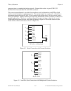
Also, the module has an internal completion network that you can use with half-bridge or
quarter-bridge networks. To use this completion network, simply connect the VEX/2 terminal to
the negative input channel of the appropriate transducer channel. In case of a quarter-bridge
configuration, you must provide an additional resistor–equal in value to your nominal strain