


Chapter 3 VXIpc 800 Series Configuration and Installation
VXIpc 800 Series User Manual 3-2 © National Instruments Corporation
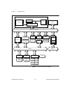
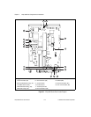
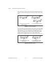
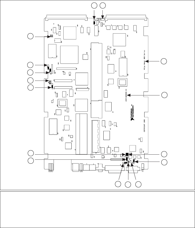
Figure 3-1. VXIpc 800 Series Parts Locator Diagram
1 Trigger In Termination (S7)
2 CLK10 Inversion (S4)
3 Ethernet EEPROM Config. (S1)
4 LPT DMA Channel (W4)
5 MITE EEPROM Config. (S9)
6 MITE Self Config. (S2)
7 Slot 0 Identification (W13)
8 CLK10 Source (S3)
9 Serial Number
10 Product Name
11 Assembly Number
12 CLK10 Direction (S5)
13 GPIB IRQ Level (S8)
14 CMOS (W2)
15 SCSI Termination (W1)
16 CLK10 Termination (S6)
3
4
1
2
5
6
7
8 9
10
11
12
13
14
15
16