


Appendix E Modifying and Installing I/O Expansion Boards
VXIpc 800 Series User Manual E-8 © National Instruments Corporation
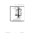
with a lock washer (hole diameter should be 0.125 in.). In either
case, use a 4-40 x 1/4 in. stainless steel panhead screw to mount the
board/bracket assembly to the front panel.
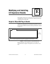
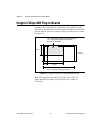
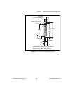
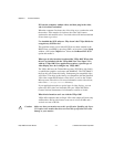
Figure E-7. PCI Board and ISA Board Installed in a VXIpc-800
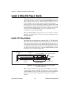
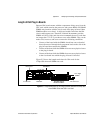
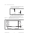
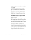
Figures E-8 and E-9 give dimensions and instructions for creating a
connector cutout and expansion bracket for a PCI board.
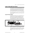
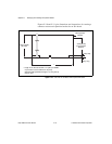
Note: In the following drawings, dimensions are given in inches and millimeters,
with the millimeter dimensions in square brackets.
Figure E-8. Side View of PCI Board with Expansion Bracket
a. PCI Board Installed b. ISA Board Installed
4.200
[106.68]
3.224 [81.89]
(I/O Connector
Window)
.300 [7.62]
(.240 [6.10])
12.283 [311.99]
PCI Expansion
Bracket