


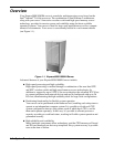
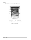
1-10 System Overview
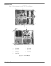
Service Processor Board
The Service Processor Board (iSP-C Board) controls power and monitors status of all
components (see Figure 1-4). The board uses a PowerPC chip as the processor for
iSP-C, memory, LAN, serial interface, and clock distribution functionality. The Service
Processor Board performs initialization of the system, RAS functions, diagnostic
functions, failure management of the system, and clock generation and distribution.
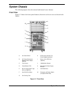
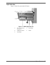
Power/Status LEDs
Three LEDs are visible on the front of the server system cabinet (see Figure 1-2):
! AC
! DC
! Status.
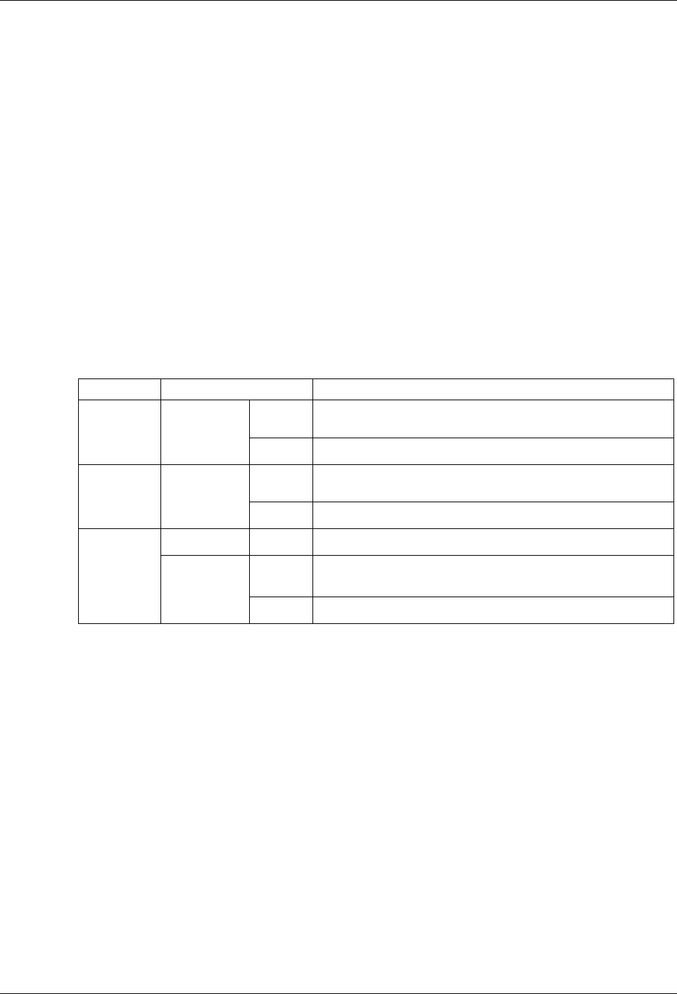
See Table 1-1 for a description of the LEDs.
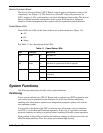
Table 1-1. Power/Status LEDs
LED LED State Description
On AC power on. AC Green
Off AC power off.
On DC power on (lights when DC48V is supplied). DC Green
Off DC power off.
Green On OS ready (one node or more).
On System is in Maintenance mode (execution of the SP “cm”
command).
Status LED
Amber
Off Failure or offline state.
System Functions
The following subsections describe select system functions.
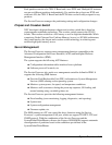
Partitioning
If your system includes two CELLV Boards and an optional core PCIX expansion unit,
your server may be partitioned at the hardware level into two distinct subsystems,
enabling each subsystem to operate as an independent computer system, each with its
own operating system.
It is possible to divide the eight-CPU system into two subsystems, each of which has
four CPUs, and let them each function separately. In this way it’s possible to allocate
processor capacity according to workload status, resulting in flexible system operation.
Each partition is physically isolated by the hardware settings; a software error does not
affect the other partitions. Thus the system can maintain high security.