E-12
NOTE: Distances may vary +/-5%.
Distance Chart
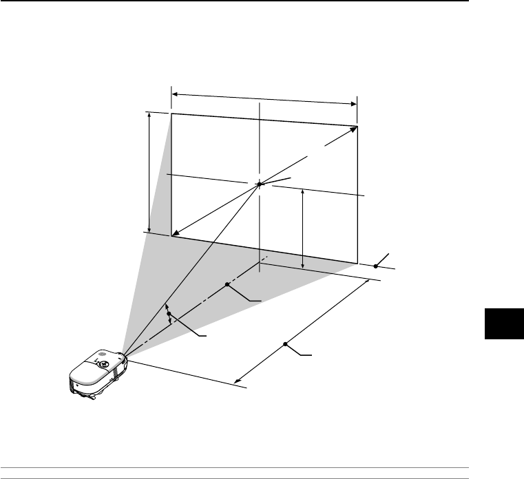
B = Vertical distance between lens center and screen center
C = Throw distance
α = Throw angle
Throw Distance and Screen Size
The following shows the proper relative positions of the projector and screen. Refer to the table to determine the
position of installation.
(
B
)
WARNING
* Installing your projector on the ceiling must be done by a qualified technician. Contact your NEC
dealer for more information.
* Do not attempt to install the projector yourself.
• Only use your projector on a solid, level surface. If the projector falls to the ground, you can be injured and the
projector severely damaged.
• Do not use the projector where temperatures vary greatly. The projector must be used at temperatures be-
tween 41˚F (5˚C) and 95˚F (35˚C).
• Do not expose the projector to moisture, dust, or smoke. This will harm the screen image.
• Ensure that you have adequate ventilation around your projector so heat can dissipate. Do not cover the vents
on the side or the front of the projector.
Rear Projection Applications
The projector has the ability to be used in a rear projection application. When used with a third party mirror and
frame system, rear projection allows you to achieve a larger image size in less distance than a traditional front
projection installation. If space constraints exist, please contact your authorized NEC reseller regarding a rear
projection solution. Refer to page E-38 on how to change the projector orientation for use in a rear projection
application.
Screen Bottom
Screen Height
Screen Width
Screen Diagonal
Screen center
Throw Distance (C)
Throw Angle (
α
)
Lens Center
2. INSTALLATION AND CONNECTIONS


