


- 107 -
Appendix: Cascade Connection
FC Switch Modules N8406-*** can be subjected to cascade connection with each other.
The following describes the cascade feature of the FC Switch Module.
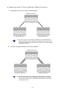
Cascade Connection
The cascade feature of the FC Switch Module is characterized as follows:
The FC Switch Modules subjected to cascade connection can share the external devices connected
to them.
The FC Switch Modules subjected to cascade connection can share the CPU blade connected to
each of the FC Switch Modules.
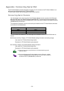
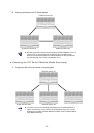
Cascade connection of up to three hops is supported.
Zoning can be provided among FC Switch Modules subjected to cascade connection.
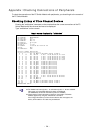
When a Fabric is constructed by cascading the FC Switch Modules, one of the FC Switch Modules
in the Fabric operates as a Principal switch. A single FC Switch Module without cascading always
operates a Principal switch.
All FC Switch Modules except the Principal switch operate as Subordinate switches.
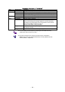
Any FC Switch Module in the Fabric can be set to be a Principal switch by
“fabricprincipal” command.
Cascading path between FC Switch Modules can be connected by multiple
connections.
Influence to the Fabric when a single cascading path failure occurred can be
avoided by making cascading path redundant or routing path between FC
Switch Modules redundant.
The maximum transmission rate among FC Switch Modules subjected to
cascade connection is 4G bps per one cascade path.
Any cascade connections of more than three hops are not supported.
The FC Switch Module can make cascade connection with only
N8406-019/020. Cascade connection with any other FC switch is not supported.
The FC Switch Modules in the same Blade Enclosure (SIGMABLADE) cannot
make cascade connection with each other.
The role of the FC Switch Module (Principal or Subordinate) may be changed
by the Fabric reconstruction.
When cascade connection is made, a Fabric construction process is done in the
FC Switch Modules connected. Influence to I/O operation in the Fabric may
occur during the Fabric construction process (including reconstruction process).
A Fabric reconstruction process occurs if the Principal switch is removed from
the Fabric by the cascading path failure.
Even if the cascading path or routing path between FC Switch Modules is
redundant, A Fabric reconstruction occurs at other switches if the Principal
switch is removed from the Fabric when a failure occurs at the Principal switch.
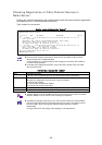
When setting of Zoning is done in the FC Switch Modules with cascading
connection, the ports used for cascading path between FC Switch Modules
must not be set zone. The cascading path is used by all zones. It may become
a cause of failure of device recognition if setting of Zoning is done with the zone
including the ports used for cascading path.