


- 46 -
4-1. Installing/Removing the FC Switch Module
Installation Procedure
Install the FC Switch Module in a Blade Enclosure (SIGMABLADE) according to the procedure
described below.
Note the following when the FC Switch Modules is installed in a Blade
Enclosure (SIGMABLADE). If more than one FC Switch Module are installed
in a Blade Enclosure (SIGMABLADE), install them one by one. After the
previous FC Switch Module is started, install the next one. Installing more
than one FC Switch Module in a Blade Enclosure (SIGMABLADE)
simultaneously may cause linkup errors to occur at the respective internal
ports.
CAUTION
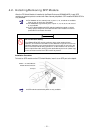
Install FC Switch Modules in a Blade Enclosure (SIGMABLADE) securely.
Install FC Switch Modules in a Blade Enclosure (SIGMABLADE) securely. Loose
installation may cause poor contact to lead smoke and/or fire.
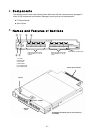
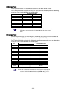
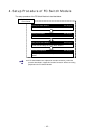
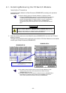
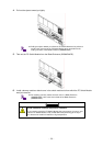
1. Check the switch module slot on the Blade Enclosure (SIGMABLADE) into which the FC Switch
Module is inserted.
The figure below shows the switch module slots into which the FC Switch Modules can be installed
on each type of Blade Enclosures (SIGMABLADE).
Slot 5
Slot 3
Slot 1
SIGMABLADE-M
Slots in which FC Switch Modules can be installed
(slot numbers 3 - 6)
SIGMABLADE-H
Slot 6
Slot 4
Slot 2
Slot 1
Slot 3
Slot 5
Slot 7
Slot 2
Slot 4
Slot 6
Slot 8
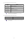
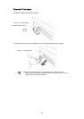
For details of switch module slots into which FC Switch Modules can be
inserted, refer to the User’s Guide attached to the Blade Enclosure
(SIGMABLADE) to be used.
FC Switch Modules can be installed in a Blade Enclosure (SIGMABLADE) if
the Enclosure is operated. For the notes on the installation, refer to the
User’s Guide attached to the Blade Enclosure (SIGMABLADE).