


Page A-2 NDA-24233 Issue 2
Appendix A VisuaLink 128/384 Engineering Guide
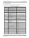
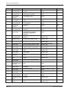
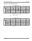
S/T Line (ISDN Connection)
Note 1:
The signal direction shown is seen from the VisuaLink 128 (DTE).
Note 2:
Pins 1, 2, 7, and 8 are not used.
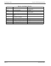
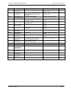
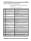
Telephone Connection
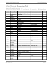
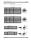
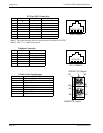
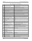
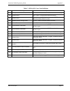
S-Video Socket Input/Output
PIN # Symbol Function Polarity
1a
2b
3 c Transmit Tip +
4dReceive Tip +
5 e Receive Ring -
6fTransmit Ring -
7g
8h
NO Symbol Function
1
2
3 L2 2W RING PIN
4 L1 2W TIP PIN
5
6
NO PIN NAME
A1 AG (Analog GND)
A2 AG (Analog GND)
A3 Y Signal IN
A4 O Signal IN
B1 AG (Analog GND)
B2 AG (Analog GND)
B3 Y Signal OUT
B4 O Signal OUT
RJ45 FEMALE
8 7 6 5 4 3 2
1
RJ11 FEMALE
6 5 4 3 2 1
O
U
T
I
N
B4
B3
SOCKET "B" (Output)
VIDEO2
B2
B1
A3
A4
A1
A2
SOCKET "A" (Input)