


110
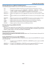
6. Using On-Screen Menu
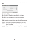
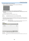
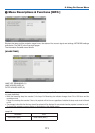
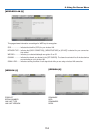
Selecting Default Source [DEFAULT SOURCE SELECT]
You can set the projector to default to any one of its inputs each time the projector is turned on.
LAST ...................... Sets the projector to default to the previous or last active input each time the projector is turned on.
AUTO ..................... Searches for an active source in order of COMPUTER1
→
COMPUTER2
→
COMPUTER3
→
COMPONENT
→
VIDEO
→
S-VIDEO
→
VIEWER
→
COMPUTER1 and displays the first found source.
COMPUTER 1 ........Displays the RGB source from the COMPUTER 1 IN connector every time the projector is started up.
COMPUTER 2 ........Displays the DVI digital source from the COMPUTER 2 IN connector every time the projector is started
up.
COMPUTER 3 ........Displays the RGB source from the COMPUTER 3(DVI-D) IN connector every time the projector is started
up.
COMPONENT .........Displays the component source from the COMPONENT IN connector every time the projector is start up.
VIDEO ....................Displays the Video source from the VIDEO IN connector every time the projector is started up.
S-VIDEO ................Displays the Video source from the S-VIDEO IN connector every time the projector is started up.
VIEWER ................. Displays slides from the USB memory device every time the projector is started up.
NETWORK .............Displays a signal from LAN port (RJ-45) or the USB Wireless LAN Unit.
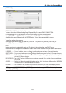
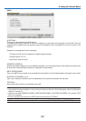
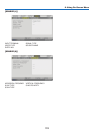
Selecting Signal Format [SIGNAL SELECT]
COMPUTER 1/2
Allows you to set [COMPUTER 1] and [COMPUTER 2] to automatically detect an incoming RGB or component
source such as a computer or DVD player. However there may be some RGB and component signals that the
projector is unable to detect. In this case, select [RGB] or [COMPONENT].
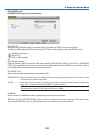
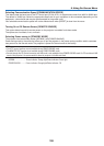
Selecting [COLOR SYSTEM]
This feature enables you to select video standards manually.
Normally select [AUTO]. Select the video standard from the pulldown menu. This must be done for Video and S-Vid-
eo Connector separately.
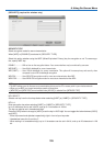
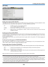
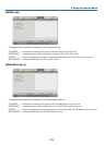
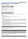
Setting MONITOR OUT Connector [OUT TERMINAL]
This option allows you to determine which RGB or component source is output from the MONITOR OUT connector
during Standby mode.
LAST ...................... The signal from the last COMPUTER 1, COMPUTER 2 or COMPONENT input will be output to the MONI-
TOR OUT connector.
COMPUTER 1, 2 ....The signal from the COMPUTER1 or COMPUTER2 input will be output to the MONITOR OUT connector.
COMPONENT .........The signal from the COMPONENT input will be output to the MONITOR OUT connectors.