


NTI VEEMUX VIDEO MATRIX SWITCH
9
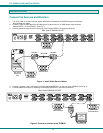
On the DB-9 female connector, pins 4 (DSR) and 6 (DTR) are shorted and pins 7 (CTS) and 8 (RTS) are shorted. Therefore, host
handshaking is bypassed and TXD and RXD are the only active signals. A straight through DB-9 cable (not null modem) will work
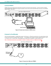
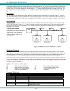
for most CPUs. To daisy chain multiple units, use NTI Matrix-Y-1 "Y" cables, except for the last unit connected. (see Fig 6). For a
pinout of the Matrix-Y-1 cable, see page 32. For straight through cable pinouts applicable to various terminal types, see page
31.
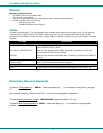
Baud Rate
The unit powers up with a default baud rate of 9600 and a fixed data protocol of 8 data bits, no parity and 1 stop bit. The baud
rate can be changed by pressing the MENU button on the front panel keypad. Then select 1 for SET BAUD RATE and select the
desired baud rate of 9600, 2400, 1200 or 300. A data protocol of 8 data bits, no parity, and 1 stop bit is used for communications.
Unit Address
To allow multiple units to be controlled from a single CPU port, the RS232 control interface is designed to allow "daisy chaining"
up to 15 units using the NTI Matrix-Y-1 "Y" cables. By setting the appropriate unit address with the keypad (the default address is
01), each unit can be given a unique address (1-15). Then the unit will only respond to commands on the bus if its address is
embedded in the command.
To set the unit address:
-select MENU on the front panel keypad
-select 2 for SET UNIT ADDRESS
-press the address number (1-15)
- press ENTER.
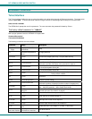
Figure 6- RS232 connection with Matrix-Y-1 cable
Command Protocol
CPU controller commands supported by the unit are defined below. All commands should be terminated with a <CR> (carriage
return). When a command is sent, the entire string is echoed back along with a response from the addressed unit as shown in the
command definitions table below. All characters in the command string should be upper case, and all numbers below 10 should
have a leading 0 (ex: 1 = 01). As command strings are sent, the inner character delay cannot exceed 500 milliseconds.
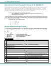
Note: To use this command protocol, the user is required to write a program that will send an entire command string all
at once, not character by character. Programs that send one character at a time (such as HyperTerminal) cannot be used
to control the VEEMUX. Alternatively, the user may use the Matrix Switcher's Control Program or SerTest to control the
VEEMUX via RS232 (see page 11).
Legend: (All numbers must be two digits)
SW : Switch (01-15) (Unit Address) MM : Save Into Memory Bank (00-99)
BR : Baud Rate Code (12,24,48,96) LL : Load From Memory Bank (00-99)
OP : Output Port (01-MAXOUTPUTS) <CR> : Carriage Return (Hex 0xD)
IP : Input Port (01-MAXINPUTS) ip
: IP address
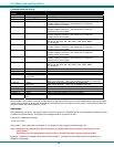
Command Definitions
Command
String
Good Response Description
CS SW,IP,OP *<CR> Connect One Output Port To Input Port
CA SW,IP *<CR> Connect All Output Ports To Input Port
RO SW,OP *<CR>IP<CR> Read Connection For Output/User Port
CC SW,MM *<CR>MM<CR> Save Matrix Connections Into Memory Bank xx
Xx=00-99
RC SW,LL *<CR>LL<CR> Restore Matrix Connections From Memory Bank
CB 00,BR None Change baud rate of serial line, BR=12(00),24(00),48(00),96(00)
Factory default is 9,600
NTI
SWITCH
CPU
RS232
First Unit
NTI
SWITCH
RS232
NTI
SWITCH
RS232
Second Unit
Last Unit
RS232
Serial Port
Matrix-Y-1
Matrix-Y-1 Matrix-Y-1