


iii
MAN067 Rev Date 2/27/2007
Specifications.............................................................................................................................................................27
IRT Troubleshooting ..................................................................................................................................................27
DDC Support................................................................................................................................................................28
Upgrade the Front Panel LCD Firmware...................................................................................................................29
RS232 Connection Cables..........................................................................................................................................31
Pinout of RS232 port on VEEMUX............................................................................................................................31
Specifications for Straight-Through Serial Cable for CPU Connection .....................................................................31
Pinout for Matrix Y-1 Cable........................................................................................................................................32
Rack Mounting Instructions.......................................................................................................................................32
Specifications..............................................................................................................................................................33
Troubleshooting..........................................................................................................................................................34
Safety Statements .......................................................................................................................................................34
Index .............................................................................................................................................................................34
Warranty Information..................................................................................................................................................34
TABLE OF FIGURES
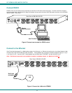
Figure 1- Install Video Source Cables................................................................................................................................................4
Figure 2- Connect a monitor to the VEEMUX ....................................................................................................................................4
Figure 3- Connect user terminal for RS232 control............................................................................................................................5
Figure 4- Connect the LAN to the VEEMUX ......................................................................................................................................5
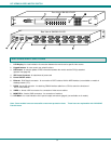
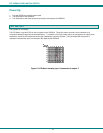
Figure 5- LED Matrix showing input 5 connected to output 5.............................................................................................................6
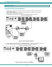
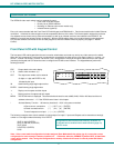
Figure 6- RS232 connection with Matrix-Y-1 cable............................................................................................................................9
Figure 7- Web interface Welcome page.........................................................................................................................................14
Figure 8- Web interface Login Prompt .............................................................................................................................................14
Figure 9- Web interface Switch page...............................................................................................................................................15
Figure 10- Web interface Setup page ..............................................................................................................................................16
Figure 11- Web interface Serial Setup page....................................................................................................................................17
Figure 12- Web interface Video Input Names page.........................................................................................................................17
Figure 13- Output Port Names.........................................................................................................................................................18
Figure 14- Web Interface Scan Mode Page.....................................................................................................................................18
Figure 15- Web interface Update Firmware page............................................................................................................................19
Figure 16- Web interface Password page........................................................................................................................................20
Figure 17- Updating the Web Server ...............................................................................................................................................20
Figure 18- Web interface Logout page.............................................................................................................................................21
Figure 19- Device Discovery Tool page...........................................................................................................................................22