DDR3THIN-MN-XXX 56 Doc. Rev. 1.11
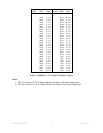
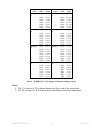
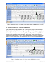
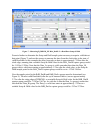
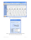
Figure 7 - Measuring B_DDR3D_XX RdA_DatHi / Lo Read Data Setup & Hold
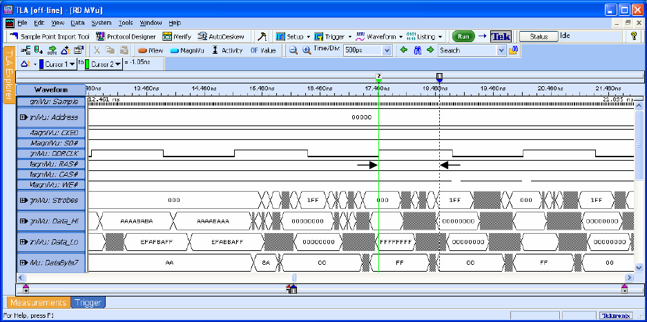
Zoom in further to determine the Setup and Hold sample point necessary to acquire valid data at
that point (Figure 7) and use the cursors to measure the time from the clock edge to the start of
valid Read data. In this example the delay from edge to data is approximately -1.05ns after the
clock edge, meaning that a suitable Setup & Hold value for the RdA_DatHi capture group would
be -1.055ns/1.289ns. Note that the Data_Lo group is valid somewhat later than the Data_Hi
group with its valid time starting at approximately 1.23ns after the clock edge, so the Setup &
Hold sample point for the RdA_DatLo capture group would be set to -1.23ns/1.465ns.
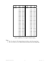
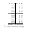
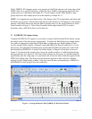
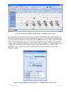
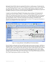
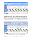
Now the sample point for the RdB_DatHi and RdB_DatLo groups must be determined (see
Figure 8). The next valid Read data (after the cycle measured above) occurs approximately
2.37ns after the rising edge of DDRCK0, so a suitable Setup & Hold value for the RdB_DatHi
capture group would be –2.383ns/2.617ns. As with the A data the Data_Lo group is somewhat
later than the Data_Hi group. The Data_Lo valid time starts at approximately -2.52ns so a
suitable Setup & Hold value for the RdB_DatLo capture group would be -2.52ns/2.754ns.
B
A


