DDR3THIN-MN-XXX 60 Doc. Rev. 1.11
used as Data Masks then the WrtMasks group should have a Setup & Hold value that matches
that of the Write Data groups.
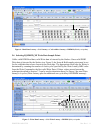
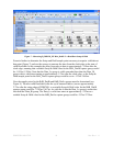
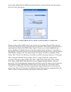
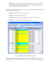
Figure 13 - Setting B_DDR3D_XX WrA_DatHi / Lo and WrB_DatHi / Lo Sample Points
Because of the speeds of DDR3 data it may be necessary to program Setup & Hold values for
each of the 8-bit groups that are associated with a given Strobe. This could be required if there is
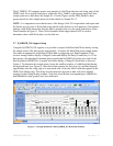
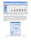
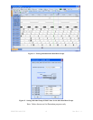
significant skew between the DDR Strobes. Figure 14 shows some of these additional data
groups (DataByte7-0) added to the same Waveform display shown in Figure 12. Note that it is
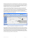
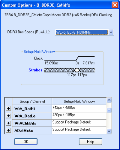
now possible to determine the skew between data groups and place these values into the Setup &
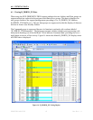
Hold Window settings in the TLA Setup window (see Figure 15). Refer to Appendix F Data
Group / Byte / Strobe Cross-Reference for details on which 8-bit groups make up a 32-bit group.
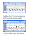
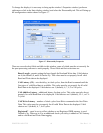
When setting the individual Setup & Hold values it is suggested that the settings for the
associated 32-bit group (RdA_DatHi, RdA_DatLo, RdB_DatHi, RdB_DatLo, WrA_DatHi,
WrA_DatLo, WrB_DatHi, WrB_DatLo) be reset to “Support Package Default”. This will
prevent the TLA from displaying warnings that conflicting values have been set for the data bits.
The Support Package Default Setup & Hold values are the same as the TLA default values –
117ps/117ps. It will also be necessary to program the Setup & Hold values for all of the 8-bit
groups in the affected 32-bit group. If conflicting Setup & Hold points are programmed then the
values will have exclamation marks beside them to denote the conflict.


