DDR3THIN-MN-XXX 58 Doc. Rev. 1.11
Setting the Setup & Hold values for acquiring Write data is a similar process. To determine the
Write Data group sample points first make an appropriate acquisition of Write data by triggering
on a Write Command. Then, as above, create a timing window display of MagniVu data and
display the Data_Hi and Data_Lo 32-bit data groups, the individual Command group signals and
the DDR3 clock that was used for the data acquisition (DDRCK0).
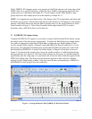
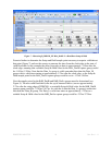
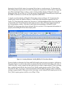
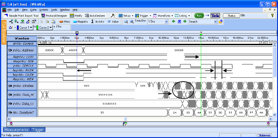
A sample waveform display of MagniVu Write data is shown in Figure 10. To determine the
sample point, locate the smallest window of valid Write data during the acquired burst (see
Figure 10). Note that in this instance the first piece of valid data happens before the rising edge it
is associated with. This shift must be taken into account or data will not be aligned properly in
the Listing display window. Note that A and B data (corresponding to ADataHi/Lo and
BDataHi/Lo data groups) have been indicated. Refer to section 5.6 for important information on
properly determining the Write data sample points.
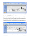
Figure 10 - Locating Minimum Valid B_DDR3D_XX Write Data Window
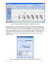
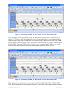
Zoom in further to determine the Setup and Hold sample point necessary to acquire valid data at
that point (Figure 11) and use the cursors to measure the time from the clock edge to the start of
valid Write data. In this example the data leads the clock edge by approximately 740ps, meaning
that a suitable Setup & Hold value for the WrA_DatHi capture group would be 742ps/-508ps.
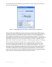
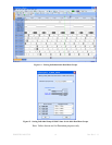
Note that the Data_Lo group is valid somewhat later than the Data_Hi group with its valid time
starting at approximately 430ps prior to the clock edge, so the Setup & Hold sample point for the
WrA_DatLo capture group would be set to 430ps/-195ps.
Write Command
Latency
ex
p
ires
Minimum
S&H
Write Data
Preamble
A A
B B


