


- 27 -
5. Setting Up the Internal-mount
Model
The internal-mount scanner is easy to install, following the
procedure described below.
5.1 Before Installing
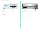
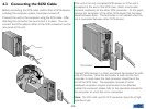
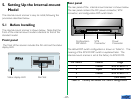
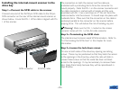
The internal-mount scanner is shown below. Note that the
front of the internal-mount model is identical to that of the
standard model.
Front panel
The front of the scanner includes the film slot and the status
display LED.
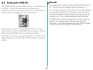
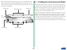
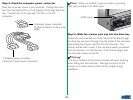
Rear panel
The rear panel of the internal-mount scanner is shown below.
The rear panel contains the DC power connector, SCSI
connector, and configuration DIP switch block.
Film SlotStatus display LED
Power
Connector
SCSI
Connector
Configuration
DIP switch
The default DIP switch configuration is shown in Table 5.1. The
meaning of the SCSI ID DIP switch is explained later. The
internal-mount scanner is set at the factory to SCSI ID #5.
DIP Switch Default Usage
1 Closed SCSI ID bit 0 = 1
2 Open SCSI ID bit 1 = 0
3 Closed SCSI ID bit 2 = 1
4 – (Not used)
Table 5.1 Factory set default DIP switch configuration